As you may have noticed in the previous post, I like hydroponic gardening. I like it because I just harvested all my brocoli, and I have a cauliflower that is turning into a monster in the waterfarm. But one thing has been a constant question for me: Could I produce more?
If you look at hydroponic forums, you’ll find that despite my success with a constant basic nutrient formula, there are people who post week by week, species specific formulas that require a large amount of tuning and care to produce the “right” mix. The more I thought about it, the more I thought, “You know what does things like this well? Computers.”
But this is a case of interfacing a computer (software) to the real world (hardware), and one thing that does that really well is the Arduino platform. Arduino is a microcontroller board with an open-hardware definition. That means that anyone can (and does) produce their own arduino-compatible boards. And along with these boards, people have designed an impressive number of “shields” that allow the microcontroller to do fun things like control stepper motors, relays, and so on.
In this case, what I want to build is a microcontroller that, when given a particular formula, dispenses the right amount of each nutrient and mixes it.
So…I began hacking.
Disclaimer: I’m a software guy. Give me a problem that I can solve with code, I’ll go at it. Hardware was new to me, even basic hardware problems like this, using pre-made components. So I learned.
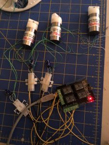
First off, I’m using the seeduino relay shield, which lets the arduino microcontroller turn on relays. Relays are in essence electric switches where a small load (like a microcontroller) can control a large one (like, say, a fan or motor). In this case, what I wanted to control were called “normally closed pinch valves.” These can cost > 120 dollars, and that…well, I write books. That should tell you my budget doesn’t include $120 valves when I’d need three.
Salvage to the rescue! I found a seller on ebay selling used ones in lots of four, and made an offer. Three weeks later, I had three functioning pinch valves (all I needed) and one dud. To be fair, the seller said they were used, and a 1:4 failure rate for salvage parts ain’t all that bad.
I wired up the relays using Molex pin connectors and ran some test code that should have turned each relay on and off in a cycle. With no valves connected, it ran fine.
With ONE valve connected, it ran fine.
With more than one, any one, the first relay would close, and the arduino would reset.
Frustrating.
So, first off I checked all the normal things: Was I drawing too much power? No.
Was I shorting out? No.
Next I started checking the voltages as each valve opened and closed, and I noticed something disturbing – when a relay closed (aka switched off), I got a wicked spike. Turns out, this is a known thing. The solution was to use a flyback diode to kill the EMF spike. This let me get two relays working, but not all three. I found a post recommending a smoothing capacitor, so I added one, and presto…three pinch valves, all operating on command.
Next phase involves building: I need to rig three jars with tubing that goes through the valves and build the code that will control them for real. To begin with, I’ll manually calibrate and just do one set formula.
So, I’m digging out the hole saws and mocking up my setup. One step at a time!

Be First to Comment